
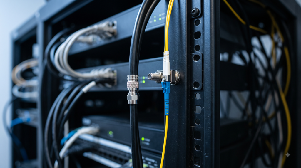
| Key Takeaways • “RF over glass” is an industry nickname for RF-over-fiber (RFoF) technology, which carries analog radio-frequency signals as modulated light through optical fiber instead of as electrical current through coaxial cable. • Coaxial cable loss increases sharply with both frequency and distance — a cable that loses roughly 5 dB per 100 feet at 1 GHz can lose more than 10 dB per 100 feet at 5.8 GHz, per published coax attenuation charts. • RF-over-fiber links are designed so signal loss is dominated by optical attenuation rather than cable length, making them suited to installations where coax loss or bandwidth becomes the limiting factor. • Commercially available RF-over-fiber hardware today spans frequency bands from roughly 1 MHz up into the tens of gigahertz, covering everything from cellular signals to millimeter-wave links. |
What does “RF over glass” actually mean?
“RF over glass” is an industry nickname for RF-over-fiber (RFoF) technology, which carries an analog radio-frequency signal as modulated light through optical fiber instead of as electrical current through coaxial cable. The RF signal itself never changes format into digital data the way a fiber internet connection would; instead, a laser is modulated directly by the RF waveform, and a photodetector on the receiving end reconstructs that same waveform from the light. The term “glass” refers to the optical fiber itself, since most fiber used in these links is drawn from silica glass rather than plastic, and engineers use the phrase informally to distinguish this analog approach from digital fiber-optic data transport such as Ethernet over fiber. commercially available RF-over-fiber converter platforms apply this approach across a wide range of frequency bands, from cellular signals up through millimeter-wave links, and are typically deployed as matched transmitter-receiver pairs rather than as a single standalone device.
Why does coaxial cable lose so much signal at higher frequencies?
Coaxial cable loss rises sharply as frequency increases, because both the resistive skin-effect losses in the conductor and the dielectric losses in the cable’s insulation get worse at higher frequencies. Skin effect pushes the RF current toward the outer surface of the center conductor as frequency climbs, which effectively shrinks the conductor’s usable cross-section and raises its resistance; the cable’s dielectric material also absorbs more energy as frequency increases, compounding the loss. A heavier cable like LMR-400 loses roughly 5.3 dB per 100 feet at 1 GHz, but that climbs to about 10.8 dB per 100 feet at 5.8 GHz — roughly double — and a thinner, cheaper cable like RG-58 loses over 50 dB per 100 feet at 5.8 GHz, according to a published coaxial cable attenuation chart. Loss is also a straight length multiplier: doubling the cable run roughly doubles the loss at any given frequency, which is why a link that performs fine over a short test bench run can fail once it is installed at its real operating distance.
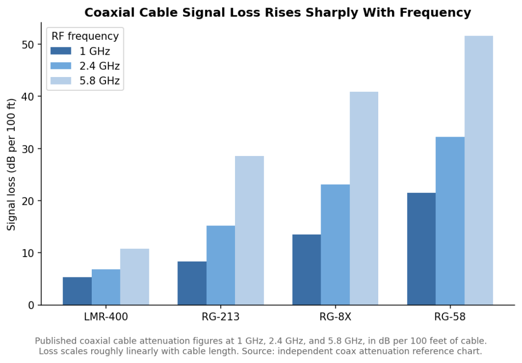
Published coaxial cable attenuation at 1 GHz, 2.4 GHz, and 5.8 GHz across four common cable types. Source: independent coax attenuation reference chart.
How does fiber optic transport avoid that frequency-dependent loss?
A fiber-based RF link’s loss is dominated by the optical fiber’s own attenuation and by the electro-optic conversion at each end, not by the RF frequency riding on the light, so performance stays much flatter across both frequency and distance than coax. That is the core advantage: instead of loss climbing sharply as frequency and cable length increase the way it does in copper, an optical link’s loss budget is set mostly by fixed factors — laser output power, photodetector sensitivity, and the fiber’s attenuation per kilometer, which for standard single-mode fiber is a small fraction of a decibel per kilometer regardless of what RF frequency is being carried on the light. This is why an RF-over-fiber link’s specification sheet is typically written around “distance limited only by optical loss” rather than around a frequency-dependent loss table the way a coax cable’s specification would be. standard RF-over-fiber link modules covering the 1 MHz to 8 GHz range are built around this principle for general-purpose signal distribution, where the same physical fiber run can carry very different RF frequencies without the loss budget changing dramatically from one frequency to the next.
How does bandwidth capacity compare between coax and fiber-based RF links?
A single strand of optical fiber can carry substantially more instantaneous RF bandwidth than a comparable coaxial cable run over the same distance, because the fiber’s usable bandwidth is not eaten away by the same frequency-dependent loss mechanisms that erode a coax cable’s usable range as distance increases. In practical terms, this means a facility that needs to distribute a wide range of RF frequencies — say, everything from low-band cellular signals up through several gigahertz of test-and-measurement signals — can often do so over a single fiber-based link where a coax-based approach would require multiple cable runs sized differently for different frequency ranges, or would need active amplification stages inserted partway through a long run to compensate for accumulated loss. Multiple RF channels can also be carried simultaneously over fiber using wavelength-division techniques, though that is a more advanced configuration than the single-channel RF-over-fiber links most facilities start with.
Where does RF-over-fiber get used instead of coax?
RF-over-fiber shows up wherever a coax run would otherwise be too long, too lossy, or too exposed to electromagnetic interference to carry a clean signal — antenna-to-equipment runs across large facilities, test labs distributing signals between racks, and installations where the cable path has to cross areas with heavy electrical noise. Because the signal travels as light rather than electrical current, the fiber run itself is inherently immune to electromagnetic interference that would otherwise couple into a long copper cable, which also means an RF-over-fiber run does not need the same grounding and bonding precautions a long coax run typically requires to avoid ground-loop noise. high-SFDR transmitter designs built for wideband signal fidelity extend this same approach into wider, more demanding frequency ranges where signal linearity matters most, such as test-and-measurement setups where even small amounts of added distortion can skew a measurement.
What should be checked before choosing fiber over coax for a specific installation?
The decision usually comes down to comparing the actual cable run length and frequency against a coax attenuation chart for the specific cable type under consideration, then checking whether the resulting loss still leaves enough signal margin at the receiving end. If the run is short and low-frequency, coax may remain the simpler and cheaper option; if the run is long, the frequency is high, or the path crosses an electrically noisy area, an RF-over-fiber link is more likely to be the practical choice once the added loss and interference risk of coax are accounted for. It is also worth checking the specific frequency range and dynamic range a given RF-over-fiber module supports, since these vary by model and need to match the signal actually being carried rather than being assumed generically. A useful way to frame the comparison is to ask what the installation would need to do to make coax work at all — larger-diameter cable, in-line amplifiers to make up for accumulated loss, additional shielding against interference — and then weigh that added cost and complexity against the cost of a fiber-based link and its transmitter/receiver pair.
Does switching to fiber change how a system needs to be maintained?
Maintenance shifts in character rather than necessarily increasing: a fiber run itself needs very little ongoing attention once properly installed and terminated, since it has no electrical continuity to test the way a copper cable does, but the transmitter and receiver electronics at each end become the components that need periodic checking. Field technicians accustomed to troubleshooting coax runs with a simple continuity or loss measurement need a different toolkit for fiber — an optical power meter or a fiber inspection scope rather than a cable tester — so a facility switching to RF-over-fiber for the first time should plan for that change in tooling and technician training alongside the hardware change itself. Connector cleanliness also matters more with fiber than with coax, since a small amount of contamination on a fiber connector face can measurably degrade a link’s performance in a way a similarly dirty coax connector typically would not.
Frequently Asked Questions
Is “RF over glass” the same thing as fiber optic internet?
No — RF over glass refers to carrying an analog radio-frequency waveform directly on modulated light through fiber, not to digital data networking, and the laser and fiber hardware used differs from typical telecom internet equipment.
Does RF-over-fiber work at the same frequencies as coax?
Yes, RF-over-fiber hardware is available across a wide range of bands, from roughly 1 MHz up into the tens of gigahertz, matching or exceeding what coax can practically carry at usable signal levels.
Is RF-over-fiber immune to electromagnetic interference?
Yes — because the signal travels as light rather than as electrical current, an RF-over-fiber link’s fiber run is inherently immune to the electromagnetic interference that can affect copper cabling.
Does fiber length affect the RF signal the way coax length does?
Optical fiber has its own attenuation, but it is far lower and much less frequency-dependent than coax, so an RF-over-fiber link’s performance stays flatter across both distance and frequency.
