
| Key Takeaways Core Mechanism: Optical delay lines convert an RF signal to optical, route it through one or more precisely measured lengths of single-mode fiber, and convert it back to RF, producing a true time delay defined by the fiber length rather than by electronic circuitry. Performance Range: Delay line designs can cover delays from a few nanoseconds up to 1,000 microseconds or more, across frequencies from 1 MHz to 67 GHz, in fixed or progressive/switchable configurations. Remote Diagnostics: RF monitoring software gives field technicians remote visibility into an RF-over-fiber system’s status, so faults in the optical or RF domain can be diagnosed without dispatching a technician with special test equipment. Shared Applications: Delay lines and RF monitoring support overlapping use cases: radar and altimeter testing, latency qualification of RF communication equipment, and long-running unattended deployments that need remote diagnostics. |
What is an optical delay line, and why use fiber for it?
An optical delay line (ODL) takes an RF input signal, converts it to a modulated optical signal, sends it through one or more sections of single-mode fiber, and converts it back into an RF signal identical to the original input, only delayed by a precise, known amount of time. That delay is determined almost entirely by the length of fiber the signal travels through, since light moves through fiber at a fixed, predictable speed. Amplification is added as needed to maintain RF performance across the delay. Using fiber for this purpose gives a delay line something electronic delay circuits struggle to match at wide bandwidths: an accurate, stable, true time delay across a very broad frequency range, without the phase distortion that can creep into purely electronic approaches.
How much delay can an optical delay line actually provide?
The achievable delay range depends heavily on frequency and on which configuration is used. At higher frequencies, physical and thermal constraints on the fiber spool limit how much delay a compact unit can practically provide; at lower frequencies, or in larger rack-mount enclosures, much longer delays become achievable.
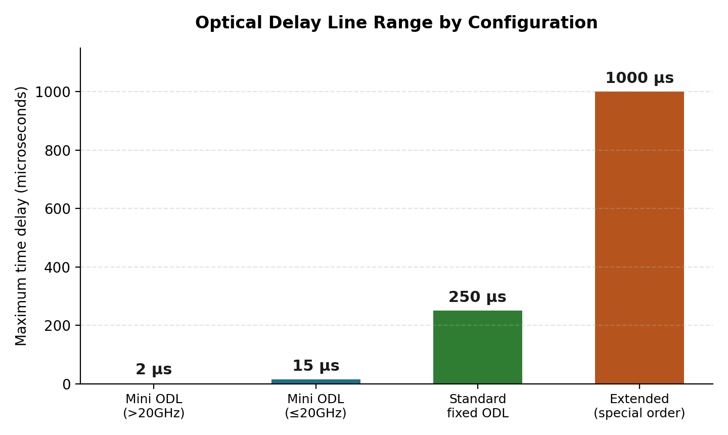
Maximum achievable time delay by optical delay line configuration.
| Configuration | Typical use case |
|---|---|
| Mini ODL (above 20 GHz) | Compact, high-frequency delay for radar and altimeter testing where space is limited. |
| Mini ODL (up to 20 GHz) | Slightly longer delay range for the same compact form factor at lower frequencies. |
| Standard fixed ODL | Rack-mount unit supporting a single, precisely defined delay value for lab or production-line use. |
| Extended / special-order ODL | Custom-built for applications needing unusually long delay values beyond standard catalog options. |
What is a progressive or variable delay line used for?
Not every application needs a single fixed delay. RFOptic’s progressive and variable optical delay lines use cascaded optical matrices with different delay sections in between, so a single unit can be switched between many possible delay combinations, up to thousands of distinct states in the highest-capacity configurations, without needing a separate fixed delay line for every value a test program requires. The unit can run standalone with no operator intervention, or be controlled externally over USB or Ethernet, which matters for automated test setups that need to step through many delay values in sequence.
How does RF monitoring keep an RF-over-fiber deployment running?
Delay lines and standard RF-over-fiber links share the same basic vulnerability: once installed, especially somewhere hard to reach, a fault in either the optical or RF domain can be difficult to diagnose without visiting the site. RF monitoring and control software addresses this by giving technicians the ability to manage, monitor, and control RF-over-fiber converters and systems locally or remotely, reducing the daily maintenance burden and letting maintenance personnel run diagnostic tests and calibration in the field without specialized test equipment.
Remote management is typically available over Ethernet using SNMP, an HTML web interface, or a REST API, while local management runs over USB. For a remote enclosure that isn’t reachable directly, an inter-facility optical link (IFL) can extend monitor-and-control access from a nearby facility, and rack-mounted delay line units often add a front-panel LCD display with simple navigation controls for on-site adjustments without a laptop.
What can RF monitoring diagnose remotely?
- Link status: whether a given transmitter/receiver pair is operating normally or has lost signal.
- Operating parameters: gain, attenuation, and other configurable settings, which can be adjusted without a site visit.
- Fault location: whether a problem sits in the optical domain (the fiber path itself) or the RF domain (the signal before conversion or after reconversion).
- Built-in test (BIT) results: self-test diagnostics that flag developing issues before they cause an outright failure.
Frequently Asked Questions
What’s the difference between a fixed and a progressive optical delay line?
A fixed ODL provides one specific, unchanging delay value. A progressive (or variable) ODL uses switchable cascaded delay sections so a single unit can be set to any of many possible delay values, useful for test programs that need to step through a range of delays.
How precise is the delay an optical delay line provides?
Precision depends on the specific design, but standard optical delay lines are commonly specified to an accuracy on the order of 0.5% of the target delay value, since the delay is defined by a physically measured length of fiber rather than an approximate electronic circuit.
Can RF monitoring software control multiple RF-over-fiber links at once?
Yes. Monitor-and-control software built for this purpose is designed to manage sets of converters and systems, not just a single link, which is part of why it supports network-based protocols like SNMP and REST rather than only a point-to-point USB connection.
Do optical delay lines need any special maintenance once installed?
Standard optical delay lines are designed for stable, largely maintenance-free operation, but pairing them with RF monitoring still allows a technician to confirm the unit is performing to specification without needing to bring dedicated test equipment on site.
