Deploying specialized BiDi transceivers cut fiber costs by up...
The integration of advanced optical delay line technology completely resolves the severe fidelity bottlenecks that traditional hardware introduces during high-precision laboratory benchmarks. Modern radar system validation, altimeter calibration, and electronic warfare testing rely on the ability to simulate realistic physical distances in a controlled laboratory environment. When evaluating a radar system designed to track high-speed targets over several kilometers, engineers must introduce precise, repeatable time delays into the signal pathway.
Historically, these delays were created using long spools of coaxial copper cables or digital radio frequency memory (DRFM) sampling loops. However, coaxial test loops introduce extreme signal loss that limits their effective range. Furthermore, digital conversion architectures manipulate the signal phase. This manipulation creates digital noise quantization that can easily mask subtle target signatures.
Structural Overhauls via Analog Fiber Transport
Advanced optical delay line technology has emerged as the clear industry standard for high-fidelity signal simulation to address these testing limitations. By routing the incoming radio frequency (RF) signal onto a precisely measured length of fiber optic cable, a dedicated module produces a real-time, phase-coherent time delay without converting the signal into the digital domain. Consequently, this optical approach keeps overall signal distortion remarkably low. This enables defense groups and aerospace labs to safely simulate long-range target profiles inside a laboratory setting.
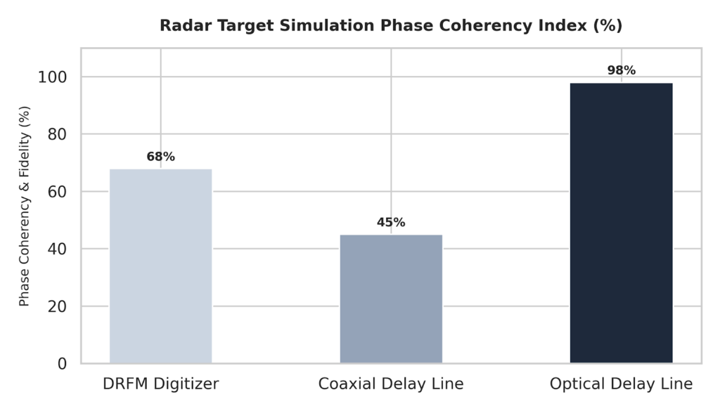
Radar Target Simulation Phase Coherency Index (%)
To understand how analog lightwave processing safeguards signal accuracy, laboratory teams must analyze phase metrics. Traditional digital sampling networks introduce conversion errors that disrupt continuous waveforms. In contrast, lightwave routing preserves pure analog behavior across ultra-wide bandwidths.
The bar chart below illustrates the simulation fidelity and phase coherency advantages achieved across diverse laboratory delay architectures:
Bar chart displaying the radar target simulation phase coherency index in percentages, demonstrating that optical delay line systems achieve ninety-eight percent fidelity compared to sixty-eight percent for DRFM digitizers.
Simulation Attribute
Digital RF Memory (DRFM) Loops
Coaxial Copper Delay Lines
Optical Delay Line (ODL) Systems
Delay Resolution Fidelity
Quantized; restricted by digitizer bit rates
Fixed length; rigid step increments
Continuous, smooth analog phase preservation
Instantaneous Bandwidth
Limited by internal sampling electronics
Broad; but restricted by high-frequency attenuation
Ultra-wideband; handles frequencies up to 40 GHz+
Signal Distortion & Noise
High; prone to digital processing artifacts
Low; but prone to high attenuation distortion
Exceptionally low; retains clean analog properties
Simulated Distance Limits
Programmable; but introduces conversion delays
Strictly limited to short ranges due to cable bulk
Supports multi-kilometer ranges in a compact footprint
The Mechanics of Lightwave-Based Time Delays
Optical systems use the fixed speed of light within a silica glass core to generate precise, predictable time delays. Because light travels through an optical fiber at a known speed of roughly 5 microseconds per kilometer of glass, engineers can calculate the exact length of fiber needed to simulate specific physical distances or radar range targets.
Therefore, advanced architectures can integrate multiple fiber spools within a single chassis using programmable optical switches. This setup allows the system to switch between different delay paths dynamically, simulating changing distances or complex multi-target environments. For example, this technology underpins the latest altimeter calibration loops. This gives aerospace teams a reliable method for testing airborne altitude radar networks safely on the ground.
Overcoming the Limitations of Digital Simulation
While DRFM setups are widely used for electronic jamming, their internal digital conversion steps introduce notable performance tradeoffs:
Phase Quantization Noise: The initial analog-to-digital conversion breaks continuous wave signatures into discrete steps, introducing quantization errors that alter the signal’s original phase.
Spurious Signal Injections: The internal clock networks inside digital samplers can introduce spurious noise frequencies into the output stream, which can confuse sensitive radar receivers.
Bandwidth Processing Bottlenecks: Processing wideband microwave profiles in real time requires massive computational processing power, which can limit the instantaneous bandwidth a digital system can handle.
Consequently, by avoiding digital conversion entirely, an optical delay system preserves the signal’s true phase and analog behavior. This provides a high-fidelity test loop that can support ultra-wideband signals up to 40 GHz and beyond.
High-Precision Testing Environments
A review of global aerospace deployment data highlights a growing integration of wideband analog optical delays across multiple demanding testing workflows:
Radar Altimeter Calibration: Simulating precise altitude profiles in a lab verifies that aircraft systems function correctly before active flight testing begins.
Electronic Warfare Range Simulation: Creating real-time, phase-coherent delay loops evaluates the vulnerability of active radar tracking systems to spoofing or jamming safely on the bench.
Space and Satellite Comms Testing: Simulating long satellite-to-ground communication paths evaluates phase stability and transit delays without launching expensive orbital assets.
To execute these high-fidelity validation loops, laboratory directors utilize programmable optical delay subsystems to simulate multi-target profiles dynamically without signal distortion. Furthermore, implementing these customized radar target simulation ODL modules ensures that phase characteristics remain perfectly intact across wide bandwidths.
Conclusion
Analog optical delay line technology provides an unmatched level of accuracy and signal fidelity for modern radar and electronic warfare testing. By utilizing the stable speed of light in optical fiber, these architectures eliminate the signal distortion, noise, and bandwidth limitations associated with digital simulation methods. As radar platforms continue to use more complex, wideband signals, the use of phase-stable optical delay networks will remain a crucial requirement. This integration is vital for securing precise, repeatable validation for critical aerospace and defense systems.