Summary: The satellite communications industry is undergoing its most dramatic transformation in decades, driven by the rapid deployment of low Earth orbit (LEO) constellations and the shift to higher-frequency mmWave bands including Ka-band, Q-band, and V-band. This article examines why these trends are creating urgent new requirements for RF signal transport within ground stations and earth stations, how RF over fiber technology addresses these needs, and how purpose-built RFoF solutions support modern SATCOM infrastructure from hub facilities to mobile and maritime terminals.
Global satellite connectivity is entering a new era. The combination of ambitious LEO constellation programs, military demand for resilient beyond-line-of-sight communications, and commercial pressure to deliver broadband anywhere on Earth is driving investment in satellite ground infrastructure at an unprecedented scale. For ground station and earth station designers, this means grappling with RF signal transport challenges -particularly at high frequencies-that require a fundamental rethink of conventional coaxial cable architectures. Exploring RF satellite communication infrastructure requirements reveals why RF over fiber has become indispensable.
The Satellite Industry’s High-Frequency Shift
Satellite communications has historically relied on C-band (4–8 GHz), Ku-band (12–18 GHz), and portions of Ka-band (26.5–40 GHz) for payload frequency assignments. The transition from geostationary (GEO) to LEO constellations, combined with spectrum congestion in traditional bands, is accelerating adoption of higher frequency allocations:
• Ka-band (26.5–40 GHz): already in widespread use for high-throughput satellite (HTS) systems, offering substantially more bandwidth than Ku-band and enabling the gigabit-class throughput that LEO broadband services require.
• Q/V-band (37.5–52.4 GHz): increasingly allocated for feeder links between ground gateway stations and satellite payloads, particularly for high-capacity GEO and MEO satellites.
• W-band and beyond (75–110 GHz): under consideration for future inter-satellite links and high-density gateway architectures, with regulatory filings already submitted by multiple operators for W-band assignments.
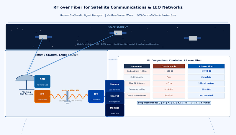
This upward frequency migration creates a clear problem for ground station signal transport. The inter-facility link (IFL)-the connection between the outdoor RF equipment at the antenna feed and the indoor modem and baseband equipment-must carry signals at increasingly high frequencies over distances of tens to hundreds of meters without degrading their integrity.
LEO Constellations: Why Ground Infrastructure Complexity Is Increasing
The LEO satellite industry has seen extraordinary growth, with SpaceX’s Starlink, OneWeb (now Eutelsat OneWeb), Amazon’s Kuiper constellation, and numerous defense-oriented LEO programs all deploying or planning large constellations. LEO satellites, orbiting at 500–2,000 km, offer dramatically lower latency than GEO systems (20–50 ms versus 600 ms for GEO), but they introduce significant new challenges for ground infrastructure:
• Rapid satellite motion: LEO satellites traverse the sky in minutes, requiring ground antennas to track continuously and hand off between satellites in the constellation.
• Large antenna apertures in dense arrays: high-throughput gateway ground stations for LEO constellations typically deploy multiple large antennas to maintain continuous coverage as satellites pass. Each antenna must be individually connected to indoor processing equipment.
• High signal density: the combination of multiple antennas, multiple frequency bands, and multiple polarizations generates a high density of parallel RF links that must be managed within the ground station facility.
For the International Telecommunication Union’s analysis of LEO spectrum coordination, ITU Radiocommunication Sector resources provide the regulatory framework within which these deployments must operate and coordinate with existing satellite users.
The Coaxial IFL Problem at Ka-Band and Above
The inter-facility link is the signal distribution backbone of a satellite ground station, connecting outdoor unit (ODU) equipment at the antenna -including low-noise block downconverters (LNBs), upconverters, and block upconverters (BUCs)-to indoor units (IDUs) containing the modems, tracking receivers, and control systems. For a small VSAT terminal, the IFL might be 5–20 meters of coaxial cable. For a gateway ground station, it might be 100–500 meters.
At L-band or low Ku-band IF frequencies, coaxial IFL is entirely practical. But as systems push IF frequencies higher-or as direct Ka-band transport becomes desirable-coaxial IFL losses become prohibitive:
• A typical LMR-400 coaxial cable has approximately 0.7 dB/m loss at 2 GHz, rising to over 2 dB/m at 10 GHz. At Ka-band (30 GHz), loss per meter becomes extreme.
• For a 100-meter IFL at Ka-band, even using the lowest-loss standard coaxial cable, signal loss would exceed 100 dB-making direct Ka-band transport via coax completely impractical beyond trivially short distances.
• The only coaxial alternative is down-conversion at the antenna to IF frequencies before the IFL, adding cost, complexity, and potential conversion loss at the outdoor unit.
RF over Fiber as the SATCOM IFL Solution
RF over fiber transforms the SATCOM IFL problem. By converting the Ka-band (or higher) RF signal to optical at the antenna feed and transporting it over single-mode fiber, an RFoF link can span hundreds of meters with less than 1 dB of optical loss-compared to the catastrophic losses of coaxial cable at the same frequency. The signal is then reconverted to RF at the indoor equipment location.
Key advantages of RFoF for SATCOM applications include:
• Native high-frequency transport: a well-designed RFoF link can transport Ka-band, Q-band, or even W-band signals directly-no down-conversion required at the antenna. This eliminates the cost and complexity of a Ka-band to IF converter at the ODU.
• EMI immunity: satellite ground stations are often co-located with other RF transmitters and electronic equipment. Optical fiber is immune to all of these electromagnetic sources.
• Low and flat signal loss versus frequency: unlike coax, optical fiber loss does not increase with RF frequency. A fiber link that works at 1 GHz works equally well at 40 GHz.
• Long reach: fiber IFL links of several hundred meters are entirely practical without amplification, enabling flexible ground station layouts where ODUs and IDUs are widely separated.
• Simplified cabling: replacing multiple coaxial cables with a single or dual fiber pair reduces installation and maintenance complexity in multi-antenna ground stations.
RFOptic’s SATCOM and mmWave Solutions
RFOptic’s product platform explicitly addresses the satellite communications market, with specific coverage of mmWave and LEO satellite applications. RFOptic describes itself as a solutions provider and R&D-driven innovative manufacturing company with global coverage, and it offers off-the-shelf links from DC to 67 GHz.
For SATCOM applications, RFOptic’s value proposition includes:
• High-frequency RF over fiber links covering Ku-band, Ka-band, and frequencies into the mmWave range — enabling direct transport of satellite IF and in some cases full-band signals without additional down-conversion.
• Subsystems and end-to-end solutions per customer requirements: SATCOM ground station architectures vary significantly between applications (gateway, hub, VSAT, military), and RFOptic’s approach of building solutions tailored to customer need allows appropriate optimization for each use case.
• Pre-sales simulation: RFOptic states that in the pre-sales stage, it builds solutions that include simulations to predict link behavior-essential for SATCOM IFL projects where link budget margins are critical.
• Global coverage: with sales offices including RFOptic Inc., its US subsidiary, providing sales services and pre and post customer support to North American customers, alongside an international distribution network.
RFOptic’s product portfolio for SATCOM also includes solutions for satellite earth station testing environments, covering both signal transport and measurement system applications.
Defense SATCOM: The Military Connectivity Requirement
Defense SATCOM represents one of the most demanding applications for high-frequency ground station signal transport. Military satellite communications systems operate across multiple frequency bands-UHF for legacy systems, X-band for protected MILSATCOM, Ka-band for wideband military communications, and increasingly Q/V-band for next-generation military HTS payloads. Resilience, anti-jam performance, and multi-band interoperability are all operational requirements.
For defense SATCOM ground terminals-whether fixed hub stations, deployed tactical terminals, or airborne and maritime platforms-the ability to transport multiple frequency bands simultaneously over a compact fiber infrastructure is a significant operational advantage. RFoF enables multi-band ground terminal architectures that would require prohibitively bulky coaxial harnesses if implemented conventionally.
Exploring specialized rf over fiber solutions for defense SATCOM reveals a growing recognition in the satellite and defense communities that native high-frequency optical transport is now the baseline architecture for serious satellite infrastructure.
Conclusion
The satellite communications industry’s shift to LEO constellations and higher-frequency mmWave bands has made the inter-facility link problem more acute than ever. Coaxial cable, practical for L-band and low-frequency IFL applications, becomes fundamentally inadequate at Ka-band and above over any meaningful distance. RF over fiber-particularly from vendors offering native transport capability up to and beyond 67 GHz-is now the default choice for forward-looking SATCOM ground station architects.
For engineers and program managers specifying new satellite ground station infrastructure, the questions to ask of any RFoF supplier are: can it transport your highest operating frequency without down-conversion? What is the noise figure and dynamic range at that frequency? Can it be customized to your specific ground station architecture? And does the vendor offer simulation-based pre-sales support to validate the link budget? Getting these questions right at the design phase avoids costly system-level revisions after hardware has been deployed.