The demand for accuracy, stability, and low-latency performance in RF systems continues to grow. Transmitter fiber optic technology provides a low-loss, interference-free method of transporting signals across long distances. Passive delay lines bring unparalleled reliability in timing control without adding power consumption or noise.
Together, these technologies enable a new era of RF system design—one where engineers can focus on innovation, not troubleshooting signal degradation or timing inconsistencies. As systems become faster and more complex, this combination ensures that timing control keeps pace with transmission demands.
If you’re building or upgrading critical RF systems, consider how passive delay lines and transmitter fiber optic solutions can work together to elevate your design.
The Rise of Transmitter Fiber Optic Technology
Transmitter fiber optic technology has transformed how we think about RF signal transport. Traditional coaxial cables are susceptible to electromagnetic interference (EMI), signal loss over distance, and bandwidth limitations. In contrast, fiber optic transmitters convert RF signals into optical signals, transmit them over single-mode or multi-mode fibers, and then reconvert them back to RF with minimal degradation.
The beauty of fiber optic transmission lies in its immunity to EMI, lower attenuation, and broader frequency support. These advantages are crucial when dealing with sensitive measurements or long-distance signal propagation. From defense systems to telecom infrastructure, engineers are rapidly shifting to fiber optic solutions to maintain signal fidelity and reduce latency.
This shift isn’t just about performance—it’s about future-proofing. As bandwidth demands increase and environments grow more electrically noisy, transmitter fiber optic solutions offer a clear path forward.
Understanding Passive Delay Lines in Signal Processing
At their core, passive delay lines are devices designed to introduce a fixed delay to an RF or analog signal without active electronic components. This delay can be critical in synchronizing signals, controlling timing in phased arrays, or replicating real-world propagation conditions in test environments.
Unlike active delay systems, which often require power, introduce noise, or suffer from thermal drift, passive delay lines offer remarkable stability and simplicity. They operate using carefully selected transmission mediums—coaxial, stripline, or fiber itself—to introduce consistent delays based on the physical length and dielectric properties of the material.
Engineers appreciate passive delay lines because of their reliability, low insertion loss, and minimal phase distortion. When precise timing is required, and the system cannot tolerate complexity or additional noise sources, passive is the way to go.
How Transmitter Fiber Optic and Passive Delay Lines Work Together
Pairing fiber optic transmitters with passive delay lines might seem like matching speed with simplicity—but that’s exactly the point. In radar systems or electronic warfare test setups, signals often need to arrive at different points at precisely staggered times. Passive delay lines can introduce those microsecond shifts reliably, while fiber optic links ensure the signal gets there cleanly, even across large distances.
The integration is straightforward but powerful: a signal originates in the RF domain, is converted to optical by the transmitter, passes through a fiber or delay module with a specific length (or an external passive delay line), and is reconverted at the receiver end. This configuration allows precise control over the timing and sequence of multiple channels.
In test labs and calibration chambers, these setups are invaluable. Passive delay lines offer deterministic behavior with no jitter, while transmitter fiber optic components preserve the purity of the waveform over great distances. Together, they deliver performance that legacy coax systems can’t match.
Passive Delay Lines: Key to Stable RF Timing
Precision matters most in environments like phased array radar or high-speed switching systems. Even tiny variations in signal timing can lead to beam steering errors or failed communications. Passive delay lines provide a dependable way to hold back a signal for an exact interval, which can be essential for phase alignment in multi-path systems.
This is particularly important in multi-antenna setups, where each antenna might require a different delay to synchronize effectively. Fiber optic systems, being modular and flexible, allow engineers to introduce delay components between transmission and reception easily—whether embedded in the optical path or used externally in the RF chain.
For anyone calibrating signal paths or simulating real-world delays, passive delay lines remain a trusted solution. The ability to fine-tune and replicate delay conditions with high repeatability is what makes them indispensable in critical RF applications.
For optimal timing in RF systems, combine transmitter fiber optic links with precision passive delay lines to ensure performance consistency.
Design Considerations for Delay Line Selection
Choosing the right passive delay line is not as simple as picking a length. Engineers must account for several variables including:
- Delay time: Usually measured in nanoseconds, determined by the physical length and velocity factor of the transmission medium.
- Frequency range: The delay line must perform consistently across the intended spectrum without introducing phase distortion.
- Insertion loss: Lower is better—especially in passive systems without amplification.
- Temperature stability: In fluctuating environments, thermal drift can alter delay time if materials aren’t properly matched.
Additionally, the choice between coaxial, fiber-based, or stripline delay lines depends on the system layout and form factor requirements. Some setups even use delay lines constructed from specially wound cables or dielectric-loaded paths to achieve compact designs.
Keep in mind that passive delay lines are fixed by nature. If dynamic or programmable delay is needed, active solutions may be required—but at the cost of added noise and complexity.
Driving Demand Across Critical Industries
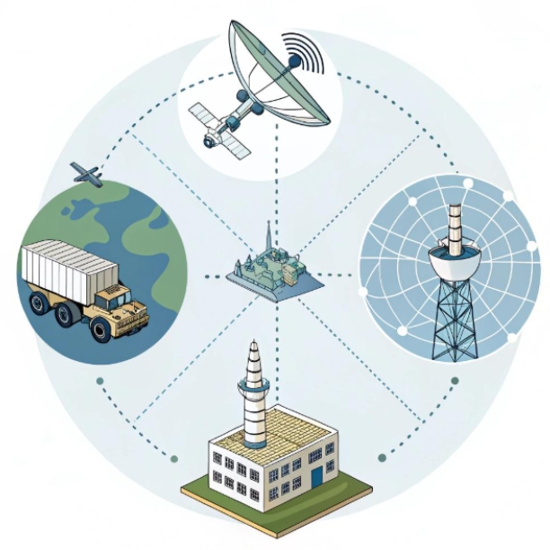
Several sectors are fueling the rise in demand for both technologies. Defense applications require secure, precise timing for radar and signal intelligence platforms. Satellite communication demands long-range, low-loss RF transport with exact synchronization. Telecom labs rely on these solutions for interoperability and device testing.
What unites these applications is the need for accuracy, repeatability, and system simplicity. That’s exactly what transmitter fiber optic setups and passive delay lines provide when implemented correctly.
By using these tools in combination, engineers can eliminate unwanted variables and design systems that behave predictably under even the harshest conditions.
Future Trends in Optical and Delay Systems
Looking forward, we can expect even tighter integration between optical RF systems and passive delay solutions. As 5G, 6G, and advanced satellite constellations increase operating frequencies into the mmWave spectrum, the precision offered by photonic components becomes even more critical.
Miniaturization is another trend. With the push toward smaller form factors in both commercial and military systems, manufacturers are developing compact passive delay modules that can slot into optical transmitter enclosures or embedded platforms.
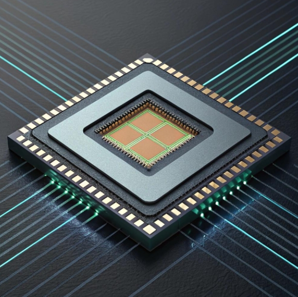
Another promising area is photonic integration. In the future, delay lines could be etched directly into optical chips, creating all-in-one signal processing platforms that merge transmission, delay, and even filtering capabilities.
Fiber optic transmitters paired with scalable passive delay lines will be essential to meet future RF timing demands.
FAQs
1. What is a transmitter fiber optic system and how does it work?
A transmitter fiber optic system converts electrical RF signals into optical signals for low-loss transmission over fiber. This helps maintain signal quality across long distances and in EMI-prone environments.
2. Why are passive delay lines used in RF systems?
Passive delay lines are used to introduce precise timing delays in RF signals. They operate without power and offer stable, low-noise performance for applications like radar, phased arrays, and test systems.
3. How do fiber optic transmitters and passive delay lines complement each other?
Fiber optic transmitters handle long-distance, interference-free signal transmission, while passive delay lines introduce exact delays needed for synchronization or calibration—making them a perfect match in precision systems.
4. What are the key benefits of using passive delay lines over active ones?
Passive delay lines require no power, generate no additional noise, offer better phase linearity, and are more stable across temperature fluctuations, making them ideal for high-reliability environments.
5. Can passive delay lines be used in optical systems directly?
While most passive delay lines operate in the RF domain, some are implemented in optical fibers as fixed-length delay segments. These can be integrated into photonic systems alongside fiber transmitters.
6. What factors should I consider when selecting a passive delay line?
Key considerations include required delay time, insertion loss, frequency range, material stability, and physical size, depending on the application’s precision and space requirements.
7. How do passive delay lines improve radar system performance?
In radar, they enable accurate beamforming and signal synchronization across antenna arrays, which is crucial for directionality and target accuracy.
8. Are transmitter fiber optic systems suitable for high-frequency applications?
Yes, modern fiber optic transmitters support wide frequency ranges, including microwave and mmWave bands, making them ideal for advanced RF applications.